Ingersoll Rand Screw Air Compressor Basics
1. What Is an Oil‑Injected Screw Air Compressor?
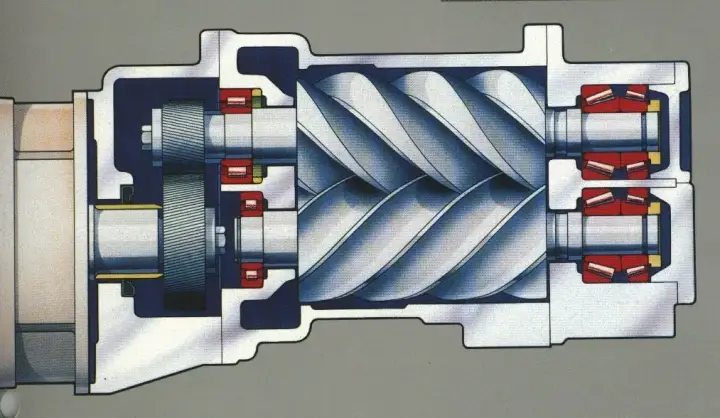
An oil‑injected rotary screw compressor uses intermeshing rotors. Air is trapped and compressed as the chamber volume decreases, while coolant seals clearances, removes heat, and lubricates bearings and gears. A built‑in pressure ratio delivers best efficiency near the rated discharge pressure.
2. Core Components & Functions
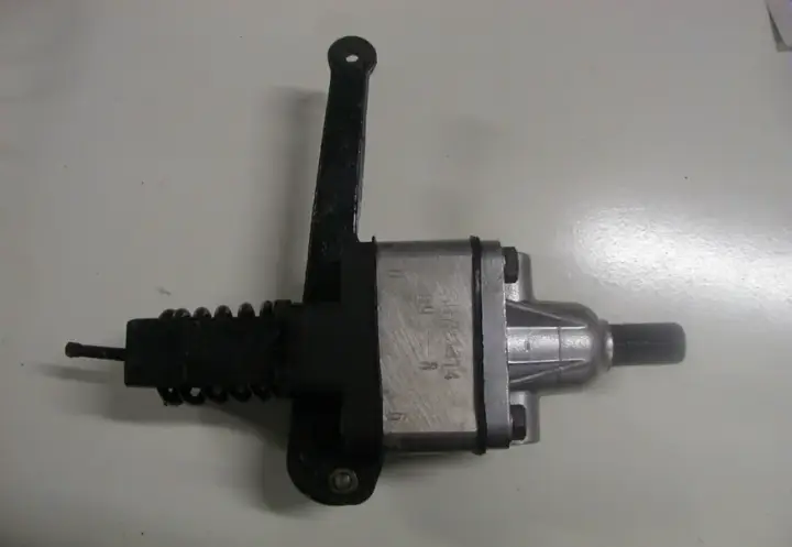
Key assemblies: air end, inlet valve, minimum pressure valve (MPV), separator vessel and coalescing element, thermostatic valve, oil filter, oil cooler/aftercooler, fan, and the Intellisys controller. The MPV maintains ~4 bar in the sump to stabilize separation; the aftercooler lowers temperature to condense moisture for removal.
3. Cooling & Lubrication System
Use the specified coolant chemistry and intervals (typical: mineral ≈2,000 h; synthetic/Ultra Coolant ≈8,000 h). Check level during warm, loaded operation and keep below half the sight glass to avoid high carryover.
4. Separation System & Oil Carryover
Primary separation occurs in the vessel; the coalescer strips fine mist to hit ~3–5 ppm. Keep the scavenge line clean and pick‑up tube height within spec. Overfilled sumps, clogged scavenge, damaged elements, or too‑low operating pressure increase oil consumption.
5. Air Path & Heat Exchangers
Discharge air passes through the aftercooler (and sometimes an intercooler). For air‑cooled units, keep fins clean; for water‑cooled, maintain flow and water quality. AirsCooler supplies efficient aftercoolers and custom heat exchangers for OEM and retrofit replacements.
6. Control Modes & Set Points
ON/OFF suits intermittent demand; modulation (regulator) throttles the intake for stable demand; auto stop/start unloads, waits, stops, and restarts at the ‘online’ set point. Configure upper/lower pressure, unload delay, and auto‑stop timers on the Intellisys.
7. Electrical & Controller (Intellisys)
Panel elements include contactors, overloads, solenoids, temperature/pressure sensors, and the HMI. Monitor package pressure, air‑end temperature, sump pressure, separator ΔP, total and loaded hours, and service reminders.
8. Protection & Safety
High‑temperature trips (typ. ≈109 °C) and overload relays protect motors and the air end. Follow local rules for separator vessel safety‑valve inspection and certification. Ducting and ambient strongly affect temperatures.
9. Troubleshooting – Quick Reference
• High discharge temperature: low coolant level, dirty cooler, clogged oil filter, faulty thermostatic valve, fan/ducting issues, high ambient, sensor failure.
• Low pressure: leaks, stuck MPV, intake/bleed valves leaking, demand exceeds capacity, set points too low, transducer/pressure switch faults.
• High current: low supply voltage, over‑pressure, clogged separator, electrical faults, air‑end issues.
• High oil carryover: overfilled sump, scavenge blockage, wrong pick‑up height, damaged coalescer, operating pressure too low, coolant degraded.
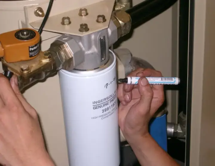
10. Routine Service Intervals
Typical: 150 h first oil‑filter change; ~2,000 h oil filter; ~8,000 h Ultra Coolant and coalescer (or earlier if ΔP > 0.6 kg/cm²); inspect inlet filters per environment; re‑grease motor bearings per spec; retorque electrical connections ~every 500 h.