Centrifugal Compressor Fundamentals Components Performance and Control
What This Guide Covers
A practical introduction to centrifugal compressors used for process and utility air: how they work, what the main parts do, how performance is formed, common losses, operating maps, anti surge control, and the auxiliary systems that keep the package reliable.
Working Principle in Plain Terms
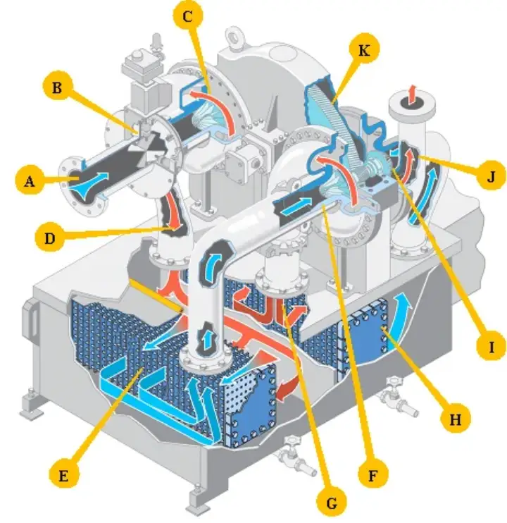
The impeller accelerates air, adding kinetic energy; the diffuser converts velocity to pressure, and each stage raises total pressure a bit more. Between stages, intercoolers remove heat so the next stage starts dense, improving efficiency and reducing work. The machine is steady‑flow—no pistons—so vibration is low and continuous duty is feasible.
Core Components and Flow Path
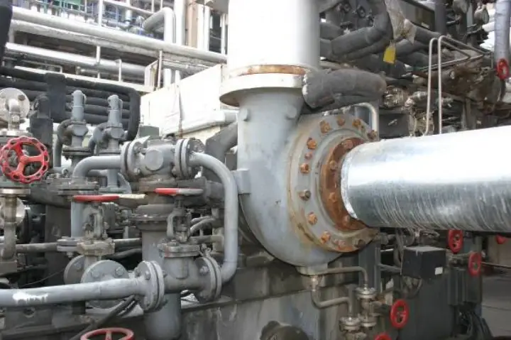
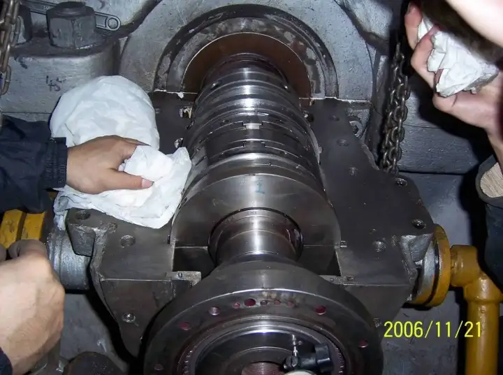
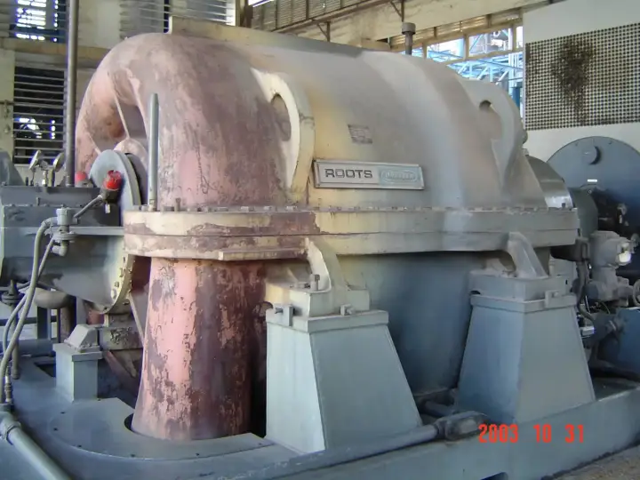
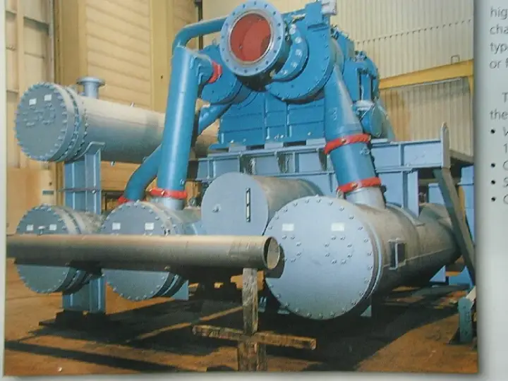
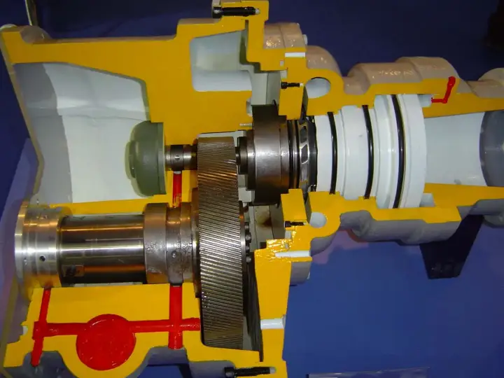
A typical three stage package includes inlet, variable inlet guide vanes, impeller plus diffuser, return channel to the next stage, moisture separator, intercooler bundles, a discharge volute and non return valve. Rotors are supported by hydrodynamic journal bearings; axial thrust is carried by a tilting pad thrust bearing. Balance disks offset residual thrust.
Impellers and Blading
Closed impellers offer higher efficiency and reduced leakage; semi open versions add strength. Backward‑leaning blades (β2 < 90°) are common in compressors because they provide good efficiency and stable characteristics. Double‑inlet wheels help manage very large flows and axial force balance.
Diffusers and Return Channels
Diffusers decelerate the flow to convert kinetic energy into static pressure with minimal loss. Designs include vaneless, vaned and straight‑wall. Good return channels minimize separation and guide the flow into the next impeller with the right incidence.
Seals and Leakage Control
Labyrinths are used for inter‑stage and wheel cover sealing; floating ring or mechanical seals can be applied at shaft ends depending on gas service. Clearances, tooth count and pressure drops determine leakage; better sealing raises efficiency but requires careful rub tolerance and materials.
Auxiliary Systems
The package relies on a forced lubrication system (reservoir, main shaft pump, auxiliary electric pump, coolers/filters, thermostatic mixing valve), seal gas or seal air supply, cooling water to intercoolers and oil coolers, condensate drains, and an electrical/control panel with protections.
Performance Curves and Operating Range
Compressor maps plot pressure ratio, corrected flow, efficiency and power. There is a left‑hand surge limit at low flow and a right‑hand choke limit at very high flow. Best efficiency sits near the design point. Ambient conditions and gas molecular weight shift the map; corrected variables are used for control.
Losses You Can Influence
Major loss types include friction/skin, separation/recirculation, incidence (when inlet angle is off), secondary flows in bends, wake losses from blade thickness, plus leakage across seals and disk friction. Practically, keeping filters clean, maintaining clearances and cleaning bundles goes a long way.
Control Philosophy
Most plants run constant header pressure. The controller modulates IGV for primary control; a blow off valve (BV) opens at low demand to keep a safe margin to surge. Some systems add speed control on the driver for wider turndown. Anti surge logic monitors corrected flow vs surge line and acts faster than manual control.
Start Up and Shutdown Essentials
Before start: verify water flow, seal air/gas pressure, oil temperature/pressure, drains, BV open 100%, IGV 0%, instruments healthy and rotation direction correct. Load only after permissives are met. For shutdown, unload first (IGV to 0%, BV to 100%), stop, keep auxiliary oil running for cool‑down, and drain condensate.
Instrumentation and Safety
Typical transmitters: suction/discharge pressures, inter‑stage temperatures, oil supply/return temperature, oil supply pressure, seal pressure, motor current, and vibration. Trips are set on high vibration, low oil pressure, over‑temperature and incorrect surge margin; alarm set‑points leave room for operator response.
Cooling Water Practices
Keep inlet water temperature within limits (e.g., ≤ 30 °C where specified) and ensure adequate flow. Trend approach temperature and pressure drop to schedule cleaning. For closed loops, maintain glycol concentration and chemistry to prevent fouling and corrosion.
Maintenance at a Glance
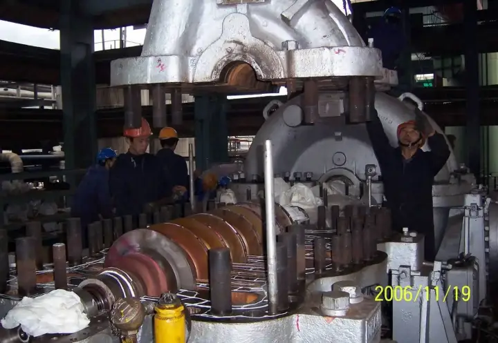
Daily: check vibration, temperatures, pressures; drain moisture. Monthly: check inlet filter ∆P and BV sealing. Semiannual: change oil filters, sample oil, inspect coupling. Annual: open and clean intercooler/aftercooler bundles; calibrate instruments; borescope impellers for fouling or damage.
Troubleshooting Guide
• Surge or instability: low inlet pressure, high inlet temperature, dirty filters, aggressive IGV throttling, undersized receiver, poor tuning.
• High discharge temperature: low CW flow/high CW temperature, fouled cooler, stuck IGV, valve leakage.
• Low header pressure: demand exceeds capacity, NRV leakage, clogged inlet filters.
• High vibration: misalignment, coupling wear, bearing issues, deposits on impellers, piping loads.
Selecting the Right Package
Match the compressor to the plant load shape and pressure needs. For large steady flows, multi‑stage centrifugal units deliver compact footprint and low vibration. Verify net usable flow at site conditions, map margin to surge, cooling utilities and maintenance access. Specify high‑efficiency intercoolers and reliable drains.
AirsCooler Cooling Solutions
AirsCooler engineers and manufactures intercoolers/aftercoolers, moisture separators and replacement bundles for OEM centrifugal packages—tailored materials (e.g., stainless steel, CuNi, aluminum fins) and geometries to reduce ∆P and enhance heat transfer, with OEM‑matched footprints for fast retrofit.