Centrifugal Compressor Design and Testing
What This Guide Covers
This guide distills a textbook on centrifugal compressors into a practitioner‑friendly summary: working principles, stage components, impellers and diffusers, intercooling and pressure‑ratio split, leakage and disk‑friction losses, axial thrust and balance disks, design workflows, and performance testing with conversion to site conditions.
Basic Working Principle
Centrifugal compressors add energy with a rotating impeller, increasing gas velocity; a diffuser then converts velocity to pressure. Multi‑stage arrangements repeat this process with intercooling to reduce specific work and improve efficiency. Compared with piston machines, centrifugal units provide smooth flow, low vibration and compact power density for large volumes.
Stage Architecture
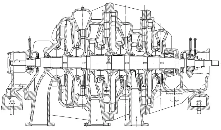
A stage comprises the inlet, impeller, diffuser, return channel and (for the last stage) a volute. The rotor is supported by hydrodynamic bearings; axial load is carried by a thrust bearing and mitigated by a balance disk. Proper aerodynamics at each element controls incidence, separation and pressure recovery.
Impeller Fundamentals
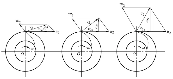
Key parameters include tip diameter, blade exit angle, blade count and width. Backward‑leaning blades improve stability and efficiency. Blade loading must respect diffusion limits to avoid stall and excessive losses. Manufacturing tolerances and surface finish influence boundary‑layer behavior.
Diffusers and Return Channels
Vaneless diffusers offer wide operating range but lower pressure recovery; vaned diffusers raise recovery at the cost of range. Return channels guide flow to the next stage with minimal turning losses. Good geometry prevents secondary flows and recirculation.
Intercooling and Pressure‑Ratio Split
Intercoolers remove heat between stages so each stage processes denser gas. Equalizing the stage pressure ratio tends to maximize overall efficiency; practical splits consider choke/surge margins, cooler pressure drops and motor limits. Shell‑and‑tube bundles with proper water chemistry keep performance stable.
Losses and Axial Thrust
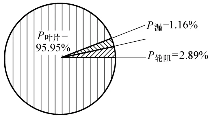
Overall losses include incidence, boundary‑layer/separation, wake, leakage across seals, and disk friction. Axial thrust arises from impeller pressure fields and is countered by balance disks and thrust bearings. Leakage control and optimized clearances are essential to efficiency.
Design Workflow Overview
Preliminary design defines flow, pressure ratio and gas properties, then lays out impeller/diffuser dimensions using similarity and experience curves. Mean‑line and 1D models estimate velocities and diffusion factors; CFD and test data refine geometry. Design must also allocate cooler duty and select materials to match corrosion and fouling risks.
Performance Curves and Testing
The characteristic map shows pressure ratio versus corrected flow with a left‑hand surge line and right‑hand choke. Tests determine head, flow, efficiency and power at controlled conditions; results are converted to reference conditions using polytropic relations and similarity rules.
Polytropic Work and Efficiency
Useful head (polytropic work) is what raises gas pressure; additional power is lost to leakage and disk friction. Polytropic efficiency relates the useful head to actual shaft work and is central to comparing stages across different conditions and sizes.
Operating Range and Anti‑Surge
Control typically targets constant header pressure via variable inlet guide vanes (IGV). A blow‑off valve (BV) adds artificial flow when demand falls, preventing surge. Anti‑surge logic compensates for ambient‑driven density changes by using corrected variables.
Instrumentation and Data Conversion
Measure suction/discharge pressures, inter‑stage temperatures, oil conditions, vibration, and IGV/BV positions. Convert test data using polytropic formulas: pressure ratio from temperature ratio and polytropic exponent; corrected flow accounts for inlet temperature and pressure.
Maintenance Focus Points
Keep inlet filters clean, intercoolers de‑fouled and drains reliable; trend vibration and temperatures; verify seal and lube systems. Plan bundle cleaning and oil analysis, and track approach temperatures to schedule cooler maintenance.
Troubleshooting Examples
• Surge: dirty filters, aggressive throttling, undersized receiver, poor tuning.
• High discharge temperature: low CW flow/high CW temperature, fouled cooler.
• Low header pressure: demand exceeds capacity, NRV leakage, clogged inlet filters.
• High vibration: misalignment, coupling wear, deposits on blades, bearing distress.
AirsCooler Solutions
AirsCooler supplies OEM‑fit intercoolers/aftercoolers and moisture separators for centrifugal compressors, using stainless steel, CuNi and aluminum fin designs to cut ∆P and improve heat transfer, enabling efficient retrofits with minimized downtime.