Centrifugal Air Compressor Principles and Operation Training
What This Training Covers
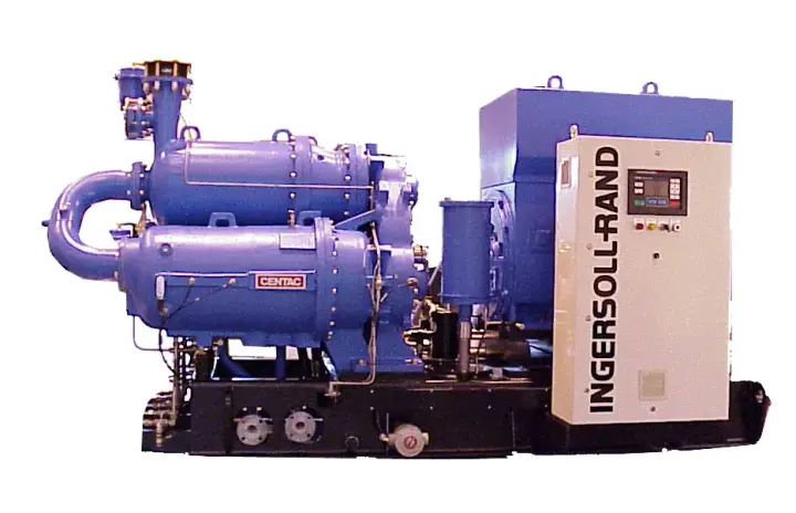
This training explains how centrifugal air compressors work and how to operate them safely: core components (IGV, impeller, diffuser, intercoolers, moisture separators and seals), lubrication and sealing systems, instrumentation, start‑up/shutdown, routine maintenance and fault diagnosis.
Core Components and Flow Path
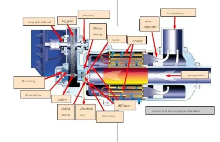
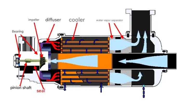
Ambient air passes the inlet guide valve (IGV) and enters Stage 1. The impeller accelerates the gas; the stationary diffuser converts velocity into pressure. An intercooler removes heat of compression and a stainless‑steel moisture separator drains condensate. The sequence repeats through subsequent stages until the required discharge pressure is achieved.
Rotor and Gearing
Each rotor assembly integrates a stainless‑steel, dynamically balanced impeller mounted on a helical pinion. Thrust loads are absorbed by hydrodynamic thrust bearings; journal bearings support radial loads. Gears are built to high AGMA quality for stability and efficiency.
Seals and Oil Integrity
Behind every impeller, a single‑stage sleeve seal cartridge sits in the bearing housing. Three floating, non‑contact carbon rings form the sealing set—one for air and two for oil. A seal‑gas buffer prevents oil migration, protecting air quality at the discharge.
Diffusers and Intercoolers
Diffusers sit between the impeller and the intercooler to convert kinetic energy to static pressure with minimal loss. Shell‑and‑tube intercoolers are designed with water in the shell side and finned tubes on the gas side for high heat‑transfer efficiency.
Moisture Separation and Draining
A stainless demister with low pressure drop sits in a low‑velocity region to enhance separation efficiency. Automatic drains remove condensate from each stage and from cooler housings before start‑up and during operation.
Instrumentation and Protections
Non‑contact vibration probes are installed near each radial bearing, feeding vibration transmitters for protection. Temperature and pressure sensors monitor each stage, the system header and the lube‑oil circuit, providing alarms and trips.
Lubrication System
A forced‑lube system supplies bearings through an oil reservoir, main shaft‑driven pump and an auxiliary electric pump for start/stop and coast‑down. A thermostatic mixing valve stabilizes oil temperature; typical oil pressure is about 0.17–0.21 MPa(g). Use clean, tested oil and maintain proper levels.
Controls and Operating Logic
Operate in constant‑pressure mode: the IGV modulates to maintain header pressure; the blow‑off valve (BV) opens at unload set‑points to avoid surge. Start‑up sequence: IGV at 0%, BV at 100%, pre‑lube pump running, verify seal‑air 0.7–1.0 MPa and water circuits; load only after checks pass. Shutdown: unload, stop, drain condensate, keep auxiliary lube running for 20–30 minutes before utilities are off.
Routine Maintenance
Record operating data; check oil level and quality (quarterly oil analysis; typical change 3 years/24,000 h); verify filter ∆P; service oil filters (6 months); lubricate or inspect the coupling; replace inlet/coalescing filters per site conditions; inspect IGV/BV actuation; review alarm history and correct root causes.
Troubleshooting Guide
• High oil temperature: low/no cooling water, high inlet‑water temp, fouled cooler, faulty thermostatic valve.
• Low oil pressure: check non‑return valves, dirty oil filters, oil‑relief setting.
• High discharge temperature: insufficient cooling water or fouled air side.
• Low system pressure: BV leakage, clogged inlet filters, excessive plant demand.
• Frequent surge: check NRV, inlet filters, set throttling point, high inter‑stage temperature or blockage, sensor errors.
• High vibration: misalignment, motor issues, worn coupling, dirty impellers, bearing/seal problems, gearing or instrumentation faults.
Best Practices Summary
Keep seal air clean, dry and oil‑free; maintain condensate drains; monitor vibration routinely; log and trend temperatures/pressures; plan preventive maintenance windows; and ensure water quality and flow to protect coolers and oil life.
Operating Modes and Set‑Points
Most plant utilities operate centrifugal compressors in constant‑pressure mode. A site header pressure—e.g., 7.5 or 8.0 bar(g)—is selected based on downstream equipment requirements and pressure drop across dryers, filters and long piping runs. The controller compares the measured header pressure with the set‑point and drives the inlet guide vanes (IGV) to maintain it. At very low demand, the blow‑off valve (BV) opens to prevent surge and to keep the unit in a safe operating area. A trim machine can run with tighter dead‑band to absorb small load swings, while base‑load machines run at higher efficiency near design point.
Start‑Up Checklist in Detail
• Utilities: verify cooling‑water availability (flow, temperature, pressure), seal‑gas or seal‑air readiness, instrument power and DCS links.
• Lube oil: confirm level, heater status and temperature; run the auxiliary oil pump to establish pressure (typ. 0.17–0.21 MPa(g)); check DP across oil filters.
• IGV/BV positions: command IGV to 0% (fully closed), BV to 100% (fully open). Confirm position feedback.
• Drains: open and confirm condensate removal from each moisture separator and cooler housing.
• Vibration baseline: ensure sensors healthy, overall vibration within allowable baseline before load.
• Bump test: jog motor to confirm rotation direction; align couplings per OEM tolerances.
• Load transition: after permissives are green, start the main motor, stabilize oil temperature/pressure, then gradually close BV and open IGV to load.
Shutdown and Short Stops
Plan a controlled unload. First, reduce load by closing IGV toward 0% while opening BV to 100% to move the operating point away from surge. Stop the motor after the flow is low and stable. Keep the auxiliary oil pump running for 20–30 minutes to cool bearings and remove heat soak. Drain moisture from separators and coolers. For short stops, keep cooling water circulating to avoid thermal stress and scale precipitation.
Anti‑Surge Control Deep Dive
A centrifugal stage loses stability when the pressure‑rise capability at low flow is insufficient, causing oscillations called surge. The control system constructs a surge map from test data and uses corrected flow and pressure ratio to estimate approach to the surge line. Protection includes: IGV limitation to avoid over‑throttling, rapid BV opening to add artificial flow, and start‑up inhibit if required sensors fail. Ambient‑driven density changes shift the surge line; therefore, inlet temperature and pressure compensation is essential. A good practice is to trend the BV activity versus demand—excessive BV cycling indicates poor control tuning or undersized storage.
Instrumentation Suite
Typical transmitters include: suction and discharge pressure, inter‑stage pressures, cooler differential temperatures, oil supply/return temperatures, oil supply pressure, seal‑gas pressure/flow (if applicable), and motor current. Vibration is measured at each radial bearing with proximity probes and processed by a monitor that provides alarms and trips at calibrated levels. Where available, bearing metal temperatures and stator RTDs are integrated.
Cooling Water Management
Efficiency and reliability depend on stable cooling water. Maintain inlet water temperature within OEM limits (often ≤ 30 °C) and provide the required flow. Monitor fouling by trending approach temperature (gas‑out minus water‑in) and pressure drop across bundles. Plan chemical treatment and periodic mechanical cleaning. For closed loops, verify glycol concentration when freezing is possible. Avoid running with low flow that can cause steam pockets and local hot spots within shell‑and‑tube intercoolers.
Seal Systems and Options
Centrifugal packages commonly use carbon‑ring gas seals with an atmospheric buffer between process and oil cavities. Some models use dry‑gas seals in process‑gas service. Seal performance depends on clean, dry buffer gas and correct clearances. Monitor leakage rates, differential pressures and temperatures; abnormal trends may indicate ring wear, contamination or misalignment. Always follow OEM reassembly procedures to maintain sealing integrity.
Motor, Starter and Electrical
Medium‑voltage motors (3–10 kV) are standard for larger units. Across‑the‑line, soft‑starter or VFD solutions may be used depending on utility rules and network stiffness. Verify protection settings, coordination with upstream breakers, and thermal model parameters. Record run‑up current/time; changes can indicate mechanical drag or electrical issues.
Data Logging and Performance Trending
Create a daily log sheet covering pressures, temperatures, IGV position, BV position, vibration, oil parameters and power. Graph trends weekly to catch gradual degradation, such as cooler fouling, filter clogging or bearing distress. Keep a commissioning baseline for comparison—this accelerates diagnosis and supports warranty claims or optimization work.
Maintenance Schedule (Typical)
• Daily/shift: check vibration, temperatures, pressures, IGV/BV function; drain condensate; review alarms.
• Monthly: inspect inlet filters, verify BV sealing, test auto drains, check cooler approach temperatures and oil DP.
• Semi‑annual: replace oil filters, sample lube oil for analysis; inspect coupling and alignment; exercise critical valves.
• Annual: open and clean intercooler/aftercooler bundles as needed; borescope impellers for deposits; verify instrumentation calibration.
• Major (multi‑year): bearing inspection/replacement per hours, gear inspection to AGMA criteria, seal cartridge refresh as indicated by leakage trends.
Troubleshooting Examples
• Frequent BV opening at stable demand: re‑tune pressure PI, increase receiver volume, check leaks or oscillating users.
• High discharge temperature: low cooling‑water flow or high inlet temperature, fouled cooler, or incorrect IGV position.
• Rising vibration on one bearing: misalignment, coupling wear, oil issues, or early bearing damage; confirm with spectrum/phase.
• Random trips: investigate loose wiring, instrument ground, noisy transmitters, or unstable 24 VDC supplies.
• Low header pressure despite full load: plant demand exceeds capacity, NRV leakage, or fouled inlet filters creating restriction.
Operator FAQs
Q1: How do I know if the compressor is approaching surge?
A: Watch the controller’s surge margin indicator and BV activity. Audible whoosh/oscillation and rapid pressure swings are late symptoms—act earlier.
Q2: Can a VFD eliminate the need for a BV?
A: A VFD can widen turndown by reducing speed but many packages still use a BV for start‑up, trip conditions or surge protection.
Q3: What oil should we use and how often do we change it?
A: Follow OEM grade/viscosity; typical synthetic turbine oils in ISO VG 32 or 46 are used, with analysis‑based change intervals (e.g., 24,000 h).
Q4: Why does IGV position differ between similar machines?
A: Calibration, ambient conditions and piping losses differ; compare against corrected flow and not raw IGV percentage alone.
Best‑Practice Checklist
• Keep seal gas clean and dry; maintain correct differential pressure.
• Ensure cooling‑water quality/flow; trend approach temperature and pressure drop.
• Maintain a clean inlet path; replace filters by ∆P, not only by calendar.
• Trend vibration and temperature; investigate small changes early.
• Validate control tuning after major maintenance or process changes.
• Document start‑up/shutdown steps and train operators with real data.